


How to wire a diesel APU to run cab electronics without idling
Instead of idling the truck to keep sleeper electronics powered, wire the diesel APU through its manufacturer-approved charging or generator circuit, with protected cab loads and starter-battery protection. The correct arrangement depends on whether the APU supplies DC charging, AC power, or both—not simply whether the engine starts.
- To wire diesel APU to run cab electronics without idling, match the APU output to the truck’s electrical system.
- Keep DC charging, inverter output, and shore power on their documented circuits; never connect competing AC sources together.
- Diesel Engine King serves used truck engine and parts buyers; APU installation requires model-specific electrical documentation.
- Protect starting capacity, verify grounding, and test the complete cab load before relying on the installation overnight.
Why this matters
An APU running beside the frame does not prove the sleeper outlets receive power. Some installations charge batteries that feed an inverter; others supply AC through a generator and distribution system. Identify that path before buying cable or opening the truck harness.
For equipment context, start with auxiliary power units for long-haul trucking. This guide covers electrical planning and commissioning, not universal terminal assignments.
Diesel Engine King is best for buyers sourcing used commercial truck engines and parts, not a substitute for an APU installation manual. Treat the following workflow as a job-planning checklist for a qualified truck electrical technician.
For a 2026 installation, match documentation to the actual truck, APU serial number, inverter, and battery arrangement. The publication date alone does not establish compatibility.
Before you start
- Collect the exact documentation. Obtain the truck’s auxiliary-power/upfitter instructions, APU installation manual, inverter or inverter-charger manual, and wiring diagrams matching the installed equipment. Include existing shore-power equipment and any battery-management system.
- Prepare the equipment and work area. Use a qualified technician, correctly rated test equipment, insulated tools, specified cable and protection, and suitable terminals. Park securely, prevent automatic starting, isolate every energy source, and follow the manufacturers’ discharge and lockout procedures.
- Identify the hidden gotcha: separate power paths. An APU charging connection does not automatically energize cab AC outlets. Existing shore power, an inverter, and an APU generator require a documented source-selection arrangement; connecting outputs together creates a backfeed hazard.
Do not run a diesel APU inside a building or where exhaust can enter the sleeper. Keep exhaust routing, ventilation, and a functioning carbon-monoxide alarm within the installation and operating checks.
Power-path selection
- Identify the output. Read the APU nameplate and schematic. Record whether the unit provides regulated DC charging, generator AC, or a combination. Do not infer the output from the presence of an alternator-shaped component or an outlet elsewhere in the cab.
- Identify the battery system. Verify the truck’s nominal voltage and battery connections. A 12 V DC system and a 24 V DC system require compatible equipment; the same connector shape does not establish compatibility.
- Inventory the loads. Record each device’s input voltage, nameplate consumption, startup requirements, and intended operating combination. Separate cab lighting and charging ports from AC appliances and sleeper HVAC.
- Choose the documented architecture. Use the table below to identify the appropriate path. Retain existing equipment only after confirming its ratings and integration requirements.
| Power arrangement | Best for | Advantage | Limitation |
|---|---|---|---|
| APU DC charging with an inverter | Cab AC electronics supplied from a compatible battery bank | Batteries buffer changing loads | Inverter demand can exceed charging output and discharge batteries |
| APU generator with AC distribution | Loads matched to the generator’s documented output | Supplies AC without requiring battery-to-AC conversion for those loads | Requires correct distribution, grounding, and source selection |
| Approved shore-power integration | Parked operation with an external electrical connection | Provides another supported supply path | Adds transfer and neutral/ground requirements; does not itself provide off-grid power |
A receptacle intended for 120 V AC must receive the voltage and frequency specified by the connected equipment. North American utility power is nominally 60 Hz, but the APU nameplate—not the truck’s location—establishes the generator output.
Expected result: You can trace every intended cab load to its source, protective device, and return path. Any unknown connection remains disconnected until identified.
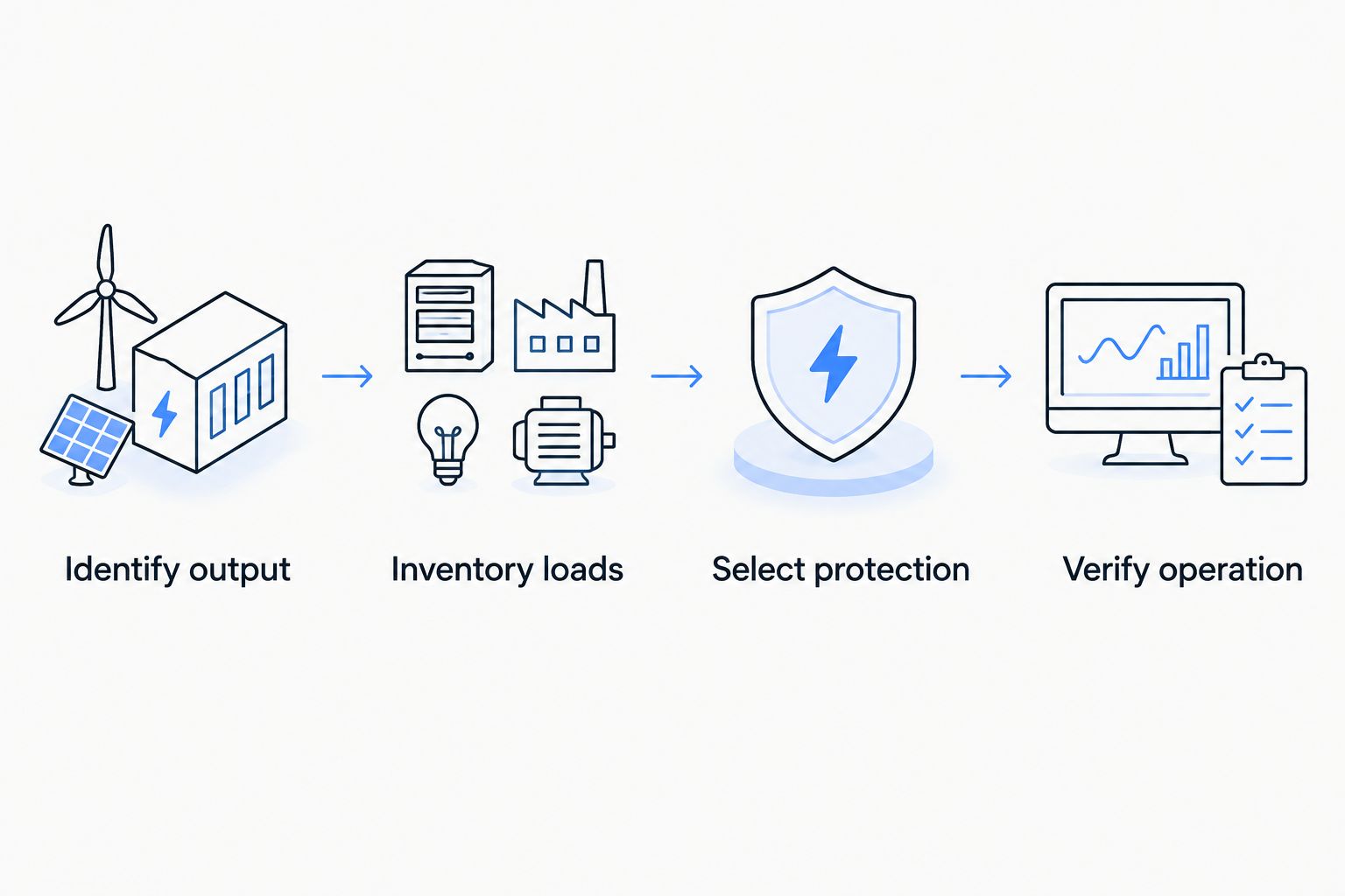
The sequence is simple: identify the source, match the loads, select protection, then test the completed system. Keep that sequence in the installation record rather than treating cable routing as the starting point.
Protected DC circuit
- Isolate all sources. Disable automatic APU starting and disconnect shore power. Follow the truck, APU, and inverter procedures for battery isolation, then verify the work area is de-energized. Turning off the dashboard ignition is not electrical isolation.
- Select protection. Have the technician size conductors, fuses, breakers, disconnects, and terminals from the equipment instructions and installation conditions. Account for current, cable length, voltage drop, temperature, bundling, and fault-interrupting requirements. A fuse protects its circuit; increasing its rating to stop nuisance opening is not a repair.
- Route the approved supply and return. Follow the specified APU charging connection and inverter feed arrangement. Protect cables from exhaust heat, moving parts, sharp edges, road debris, and cab movement. Use suitable bulkhead protection and strain relief.
- Preserve battery monitoring. Connect returns at the documented points so current passes through any required battery-monitoring sensor. Do not bypass a sensor or assume every chassis point is an acceptable return.
- Protect starting capacity. Use the manufacturer-approved isolation, battery-management, or low-voltage-disconnect arrangement. A shared starting bank needs protection against cab loads consuming the energy required to restart the truck.
Expected result: The installed DC circuit matches the approved schematic, has protection at the required locations, and preserves the truck’s intended battery monitoring and starting protection.
Do not splice cab power into an engine-control-module supply, communication circuit, or unidentified ignition wire. Diesel Engine King supplies used commercial truck engines and parts; an engine ECM is not an auxiliary-power distribution device.
Keep a 2026 wiring record showing cable routes, protective-device ratings, connection locations, and installed equipment identifiers. Use the equipment manuals’ torque specifications, not a generic terminal-tightening rule.
AC distribution and source selection
- Choose the approved cab supply connection. Connect inverter or generator output only through the distribution arrangement specified for that equipment and truck. Never energize a cab receptacle through a homemade male-to-male cord.
- Separate competing sources. Where shore power, generator output, and inverter output serve shared circuits, use a compatible, correctly configured transfer arrangement. An inverter-charger with an internal transfer function still requires verification against its own wiring instructions.
- Confirm grounding and neutral treatment. Have the technician establish equipment grounding, bonding, and any neutral switching from the complete system design. Do not add a neutral-to-chassis connection simply because an outlet tester suggests a problem.
- Verify protective devices. Confirm branch-circuit protection and required ground-fault protection. Use the installed device’s documented test procedure; never defeat protection to keep an appliance operating.
- Label the circuits. Mark which outlets operate from auxiliary power and identify disconnects and source-selection equipment. Keep vehicle-required circuits outside the cab-electronics modification unless the truck manufacturer explicitly supports their inclusion.
Expected result: Each supported AC circuit receives power from its selected source without an unintended connection to another source. Grounds, neutrals, and protection match the documented configuration.
For your 2026 commissioning sheet, record the source supplying each outlet in every supported operating mode. An outlet that works on shore power but not on the APU needs a power-path diagnosis, not an improvised jumper.
Load verification and handover
- Inspect before energizing. Check polarity, termination quality, terminal covers, cable supports, protection, and separation from heat or abrasion. Complete the manufacturer’s required electrical tests before restoring power.
- Restore power in the documented sequence. Keep cab loads off initially. Start the APU outdoors under its operating instructions, then verify its charging or generator output at the prescribed test points.
- Add loads individually. Enable the inverter or distribution system according to its manual. Operate each intended device, then test the combination you actually use while parked. Include appliance startup behavior, not just steady operation.
- Check the battery trend. Measure whether the bank charges, remains supported, or discharges under the planned load. Battery voltage alone does not establish charging capacity; use appropriate current measurements and account for the battery-management system.
- Test supported mode changes. Verify APU stop, inverter operation, shore-power selection, and truck-engine operation where the manuals permit those combinations. Test automatic functions only under their documented commissioning procedures.
Expected result: Cab electronics operate with the main engine off, protection remains functional, and the battery system behaves as designed. Stop testing for abnormal heating, burning smells, repeated protective trips, or unstable output.
Retain the completed 2026 test record with the truck. Include actual measurements and the tested load combination; do not copy another truck’s results.
Automatic cab power when battery charge drops
Automatic APU starting is a separate workflow, not a reason to bypass starter-battery protection. Use it only when the installed APU controller and truck integration explicitly support battery-maintenance operation.
- Verify the controller’s supported start conditions, battery sensing point, and required interlocks.
- Configure the documented battery-maintenance function using the exact manual for that controller. Menu labels and permitted settings vary by equipment.
- Check how the system handles shore power, truck-engine operation, service mode, and shutdown faults.
- Perform the manufacturer’s controlled functional test while attended and outdoors.
Expected result: The APU responds to its supported battery-maintenance condition and respects all required inhibits. Do not simulate a low-battery condition by deeply discharging the starting bank.
Best for: Approved unattended battery-support operation. The advantage is automatic response; the limitation is dependence on correct sensing, controller configuration, fuel, and maintained equipment. Automatic starting does not increase the APU’s electrical capacity.
Troubleshooting
The APU runs, but cab outlets remain dead
Trace the selected AC path: output protection, inverter enable state, transfer equipment, and branch protection. A charging-only installation still needs a functioning inverter to supply AC loads. Inspect and test with the system safely isolated where required.
Electronics reset when an appliance starts
Check startup demand against source capability, then measure voltage drop through both supply and return paths under load. Inspect connections and battery condition. Do not fit a larger breaker unless the complete circuit design supports it.
Starting batteries discharge overnight
Measure cab demand and APU charging contribution during the actual operating combination. Check charging faults, battery health, isolation operation, and low-voltage protection. A running APU does not guarantee a positive charging balance.
A ground-fault device trips during source changes
Disconnect the affected loads and have the technician inspect the appliance and transfer/bonding configuration. Follow the protection device and source-equipment procedures. Removing a ground connection or bypassing the device is not an acceptable fix.
The APU will not start automatically
Check the controller’s reported inhibit or fault against its manual. Confirm supported operating mode, battery sensing, service lockout, and required interlocks. Never jumper an unidentified interlock to force a start.
Customize your workflow
After commissioning, expand the installation record rather than adding unplanned loads. List permitted appliance combinations, supported source modes, shutdown procedures, and inspection points so another driver can operate the truck correctly.
Add cable-condition checks and electrical fault review to your diesel auxiliary power unit maintenance routine. Reassess capacity before adding another inverter-fed appliance or changing the battery bank.
FAQ
Can I wire a diesel APU directly to my cab outlets?
Only an APU with a compatible AC output can supply those outlets through its approved distribution arrangement. A charging-only APU needs a compatible inverter to convert battery DC into AC.
Can an APU charge batteries while an inverter runs cab electronics?
Yes, when the equipment supports that arrangement and the installation follows its wiring instructions. If inverter demand exceeds the charging contribution, the battery bank still discharges.
Do all diesel APUs provide 120 V AC?
No. Identify the installed APU’s output from its nameplate and wiring documentation; diesel operation alone does not establish its electrical output.
What wire size should I use for a diesel APU?
Use the conductor size specified for the equipment and installation conditions. Current, circuit length, temperature, routing, voltage drop, and protection determine the selection; there is no universal APU cable size.
Can shore power and an APU feed the same sleeper outlets?
Yes, through a compatible, documented transfer arrangement. Never connect independent AC outputs directly together or backfeed an outlet.
Will an APU keep my starting batteries from going dead?
Not automatically. Charging capacity, cab demand, battery condition, and correctly configured starting-battery protection determine whether sufficient starting capacity remains.
Can I install diesel APU wiring without the original manual?
Do not proceed without documentation matching the installed equipment. Obtain the correct diagrams and have a qualified truck electrical technician verify the integration before energizing it.
One last thing
An illuminated outlet is not proof of a balanced electrical system. An inverter can keep cab electronics running while the battery bank quietly discharges. Your final acceptance check is the measured battery trend under the intended parked load—not the sound of the APU engine.
Keep Diesel Engine King truck-parts sourcing separate from electrical compatibility decisions. Match every installed component to the documented power path before putting the truck back into overnight service.

