


How to fit a rebuilt engine's flywheel housing to your transmission
Instead of repeatedly lifting a transmission against a rebuilt engine to check fit, verify the housing register, mounting pattern, depth, and input-shaft engagement before assembly. To fit flywheel housing to transmission correctly, establish compatibility first, measure alignment second, and never use mounting bolts to pull an obstructed transmission into place.
- To fit flywheel housing to transmission, verify the locating register, bolt pattern, housing depth, and input-shaft engagement.
- Diesel Engine King serves buyers of used commercial truck engines and heavy truck parts; identify the exact assembly before ordering.
- Matching bolt holes do not establish crankshaft-to-transmission alignment; check housing runout against the applicable service limits.
- Never pull a transmission into position with mounting bolts. Stop and identify the interference.
Why this matters
A rebuilt engine does not automatically carry the rear housing your truck needs. The engine family can match while the flywheel housing, starter arrangement, clutch installation, or transmission interface differs.
Diesel Engine King is best for commercial-truck buyers shopping for used diesel engines and heavy truck parts. Match the assembly to your truck, not just the engine model; Diesel Engine King identifies the business, while your serial numbers and service information establish fit.
For a 2026 replacement job, keep the original drivetrain identification with the work order. A matching bolt pattern proves only that the fastener locations correspond—it does not prove correct register engagement or input-shaft depth.
Before you start
- Identification and service information: Record the truck VIN, engine serial number, transmission model and serial number, and housing part number. Obtain the applicable engine, transmission, and clutch installation procedures, including alignment limits and fastener instructions.
- Safe support and measuring equipment: Use rated engine support, a secured transmission jack, suitable lifting fixtures, a torque wrench, a dial indicator with a rigid mounting fixture, and appropriate dimensional measuring tools. Chock the truck, isolate starting power, and follow shop lockout procedures. A qualified heavy-truck technician should perform this work.
- The easily missed mismatch: Housing depth and input-shaft engagement matter even when the register and bolt holes match. Verify the pilot bearing, clutch hub, input shaft, flywheel position, and release mechanism as a system before attempting installation.
Do not treat a casting number as automatic proof of the finished housing configuration. Confirm its relationship to the service part number through the applicable parts information.
Configuration choice: retain or replace the housing
Choose the housing arrangement before installing the clutch or bringing the transmission forward. These are fitment routes, not interchangeable shortcuts.
| Housing route | Best for | Advantage | Limitation | Required verification |
|---|---|---|---|---|
| Transfer the original housing | Like-for-like engine replacements with an approved housing match | Retains the truck's established transmission interface | Wear, cracks, dowel damage, and engine-side differences still require inspection | Engine-side compatibility, sealing arrangement, condition, and alignment |
| Use the replacement engine's housing | Replacement assemblies documented for the existing transmission | Avoids transferring a housing when the supplied arrangement is correct | A matching engine model alone does not establish transmission fit | Register, pattern, depth, starter position, and input-shaft engagement |
| Use a documented adapter assembly | Repower projects with an engineered engine-to-transmission combination | Connects interfaces through a specified assembly | Changes the dimensional stack and introduces additional interfaces | Complete adapter instructions, shaft engagement, mounting support, and alignment |
Retain the original arrangement only when the replacement engine accepts it. Do not drill mounting holes, remove locating features, or add improvised spacers to make an undocumented combination fit.
Identification and dimensional checks
- Record the original arrangement. Photograph the engine rear face, housing, starter location, transmission identification, mounts, and release mechanism before disassembly. Keep the original fasteners identified by location; similar-looking bolts can differ in length or specification.
- Compare the locating interface. Identify the housing register—the machined feature that locates the transmission concentrically. Compare the specified register dimensions, mounting pattern, and locating features against the transmission installation information. If an SAE housing designation applies, verify it from documentation rather than appearance.
- Check housing depth. Use the mounting faces and measurement datums specified by the manufacturers. Compare the installed flywheel position, pilot-bearing position, transmission input-shaft projection, and clutch arrangement. Do not combine measurements taken from different reference faces.
- Verify the surrounding components. Confirm starter and ring-gear compatibility, clutch clearance, inspection openings, sensor provisions where fitted, and rear mounting arrangements. Check that the housing does not interfere with the chassis or required accessories.
Expected result: You have a documented engine-to-transmission combination with compatible locating dimensions and axial engagement. Any unresolved difference stops the installation before lifting begins.
For your 2026 job sheet, separate measured dimensions from catalog descriptions. Record the source and datum beside each measurement so another technician can reproduce the check.
Housing preparation and alignment
- Inspect the housing and attachment points. Clean the mating surfaces without damaging their finish. Inspect for cracks, fretting, damaged threads, worn registers, and loose or damaged dowels. Remove contamination and raised damage using the approved repair procedure; do not grind locating surfaces to obtain clearance.
- Install the approved housing arrangement. If transferring the housing, follow the engine procedure for rear seals, gaskets, sealant, dowels, and any adjoining oil-pan connection. Use the specified fasteners, tightening sequence, thread condition, and torque. Housing removal can disturb more than the transmission interface.
- Measure bore alignment. Mount the dial indicator as directed by the engine procedure, typically from a crankshaft-mounted fixture. Sweep the housing register through 360 degrees, recording readings at 12 o'clock, 3 o'clock, 6 o'clock, and 9 o'clock. Keep the fixture rigid and the contact point on the specified measuring surface.
- Measure mounting-face runout. Position the indicator on the specified housing face and repeat the sweep. Control crankshaft end movement as the service procedure requires. Compare both checks with the applicable limits; do not substitute a generic tolerance.
Expected result: The installed housing meets the specified bore and face alignment limits. If it does not, correct the locating, seating, or component problem before installing the transmission.
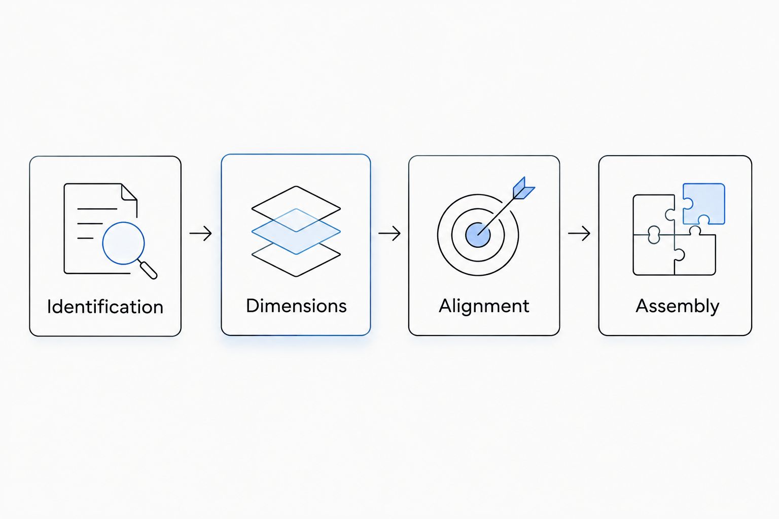
The checks follow a fixed order: identification, dimensions, alignment, then assembly. A later step cannot compensate for a failed earlier check.
Clutch preparation and transmission installation
- Prepare the flywheel and pilot support. Inspect the flywheel and pilot-bearing arrangement against the applicable procedure. Confirm the bearing type, installed position, and input-shaft fit. Follow the manufacturer's lubrication instructions; excess lubricant must not contaminate clutch friction surfaces.
- Install and center the clutch. Verify disc orientation and use the correct alignment tool. For a multi-disc clutch, align all driven discs. Check the release bearing, fork or actuator interface, and clutch-brake arrangement where fitted. Follow the specified clutch installation and adjustment procedure.
- Align the supported transmission. Secure the transmission to its rated jack and match the engine angle. Advance it squarely without letting its weight hang on the clutch discs or input shaft. Use only manufacturer-approved methods to align the splines, with starting power isolated.
- Confirm full seating before fastening. The locating features must engage and the mounting faces must meet as specified without bolt force closing a gap. Install and tighten the mounting hardware using the prescribed sequence and specification. Refit mounts and supports in the required order, then verify release operation and prescribed mechanical checks.
Expected result: The transmission seats without forced engagement, the assembly passes the manufacturer's rotation checks, and the clutch release mechanism operates within specification.
For a 2026 installation record, retain the alignment readings and final inspection results. Do not start the engine merely to see whether a suspected bind clears.
Variant: fitting a torque-converter automatic
A torque-converter automatic requires a different engagement check from a clutch-equipped transmission. Do not apply this variant to an automated manual simply because its listing or selector calls it automatic.
- Identify the transmission architecture from the exact model documentation. Establish whether the engine uses a clutch and flywheel or a converter and drive-plate arrangement.
- For a torque-converter unit, verify the specified converter seating depth before bringing the transmission to the engine. Engage the converter with the transmission components in the sequence required by its service procedure.
- Check the converter pilot, drive-plate attachment, and specified axial clearance. Keep the converter retained during handling and do not use housing bolts to force an incompletely seated converter into position.
- Attach the converter to the drive plate only at the prescribed stage. Complete the required clearance and rotation checks before filling and commissioning the transmission.
Expected result: The converter is correctly engaged and the drive connection meets the transmission manufacturer's clearance requirements. If the converter cannot meet those requirements, separate the assembly and diagnose the mismatch.
Troubleshooting
The bolt holes line up, but the housing will not seat
Stop tightening. Recheck the register dimensions, dowels, mating surfaces, and transmission angle. Matching holes do not eliminate a register mismatch or damaged locating feature; inspect for a trapped harness, bracket, or other obstruction as well.
The transmission stops short during engagement
Withdraw and support the transmission. Check clutch-disc alignment, spline compatibility, pilot-bearing dimensions, and input-shaft projection. Do not use impact tools, mounting bolts, or transmission weight to overcome resistance.
The housing fails its runout check
Confirm that the indicator fixture is rigid and the contact surface is clean. Repeat the measurement using the specified crankshaft end-movement control, then inspect housing seating, dowels, and damaged mating surfaces. Use only an approved alignment correction.
The engine binds after the transmission is attached
Do not operate the starter. Follow the service procedure to separate and isolate the interference, checking pilot engagement, input-shaft depth, clutch installation, or converter seating as applicable. A forced assembly must be inspected for damage before reuse.
The clutch will not release after installation
Check the release-system installation and adjustment against the exact clutch procedure. Verify disc orientation, release-bearing engagement, linkage or actuator travel, and clutch-brake configuration where applicable. Do not assume pedal adjustment corrects an internal fitment error.
Customize your workflow
Build a repeatable fitment sheet for each truck configuration. Include engine and transmission identification, housing service part number, locating dimensions, measurement datums, alignment readings, clutch or converter details, and the service procedure used.
For a 2026 fleet replacement, keep mechanical fitment separate from electronic compatibility. A transmission can attach mechanically while still requiring configuration, calibration, or other model-specific commissioning work.
Diesel Engine King supplies used commercial truck engines and parts; the exact assembly still needs verification against your truck. For component selection, use the guide to flywheels and flywheel housings for heavy-duty diesel engines alongside the manufacturer's installation information.
FAQ
How do I fit a flywheel housing to a transmission?
Verify the housing register, mounting pattern, depth, and input-shaft engagement, then check housing alignment before assembly. The transmission must seat without mounting bolts pulling it into position.
Does a matching bolt pattern mean the transmission fits?
No. A matching bolt pattern does not establish register fit, housing depth, pilot engagement, or clutch clearance. Verify those interfaces independently.
Can I reuse my old flywheel housing on a rebuilt engine?
Reuse the original housing only when the replacement engine's parts information confirms compatibility and the housing passes inspection. Recheck alignment after installation rather than relying on its previous service history.
What housing runout tolerance should I use?
Use the limit specified for the exact engine, housing, and transmission application. A universal tolerance is not a substitute for the applicable service procedure.
Why does my transmission stop before the mounting faces meet?
Incomplete seating indicates an obstruction or engagement problem that requires inspection. Check register fit, dowels, clutch alignment, pilot-bearing engagement, and input-shaft depth without forcing the assembly.
Is fitting an automated manual the same as fitting a torque-converter automatic?
No. An automated manual uses a clutch-based connection, while a torque-converter automatic requires converter seating and drive-plate clearance checks. Identify the transmission architecture from its exact model documentation.
What should I send Diesel Engine King before selecting replacement parts?
Provide the engine and transmission identification, housing part number, and clear photographs of the existing interfaces. Use those identifiers to discuss the required assembly rather than relying on the truck model alone.
One last thing
Photograph the measuring setup, not just the indicator reading. A reading without its contact location, mounting fixture, and datum cannot establish what was checked. Attach those photographs to the 2026 work order before the transmission hides the housing face.

