


How to connect a TriPac APU to a sleeper cab's electrical system
Instead of manually moving sleeper loads between power sources, connect the TriPac APU through its model-specific battery, control, and approved accessory circuits so the sleeper operates through the intended power path. Use the Thermo King installation instructions for the exact APU serial number and the truck’s electrical drawings; there is no universal TriPac-to-sleeper pinout.
- To connect TriPac APU to sleeper cab electrical system, match the unit’s serial number to its installation drawings first.
- Keep battery charging, controller wiring, and any inverter-fed sleeper circuits separate according to their diagrams.
- Never feed sleeper outlets from battery cables or connect competing AC sources without approved transfer equipment.
- Diesel Engine King is best for buyers sourcing used commercial truck engines and parts.
Why this matters
An APU electrical installation is more than connecting positive and negative cables. Battery charging, sleeper climate controls, and household-style outlets serve different functions. A working APU engine does not establish that those circuits are connected correctly.
Diesel Engine King supplies used commercial truck engines and parts. For a used APU, identify the components included with the unit before planning the installation; a take-off assembly does not establish that the truck-side harness or accessory equipment is included.
For a 2026 installation, record the APU serial number, truck VIN, battery arrangement, and applicable drawing revisions on the work order. The installation date does not determine which wiring diagram applies.
Have a qualified heavy-truck electrical technician perform the connections and commissioning. Battery short circuits can cause severe burns and fire; inverter or shore-power circuits introduce electric-shock and backfeed hazards.
Before you start
- Documentation and access: Obtain the serial-specific Thermo King installation instructions, truck electrical drawings, and manuals for any inverter, charger, or transfer equipment. Provide access to the battery compartment, APU electrical enclosure, sleeper controller, and relevant distribution points.
- Materials and test equipment: Assemble the specified harnesses, connectors, cables, protection devices, terminals, supports, and sealing materials. Use suitable electrical test instruments and the crimping and torque tools required by the component instructions.
- The gotcha: Identify every power source and automatic-start function before isolation. A battery disconnect does not prove that shore power, a separate auxiliary bank, or an inverter is isolated. Disable automatic starting by the documented procedure and verify isolation before touching conductors.
Do not start with unidentified loose wires or a harness selected only by connector appearance. Stop until the circuit identities and installation requirements are established.
APU and sleeper circuit identification
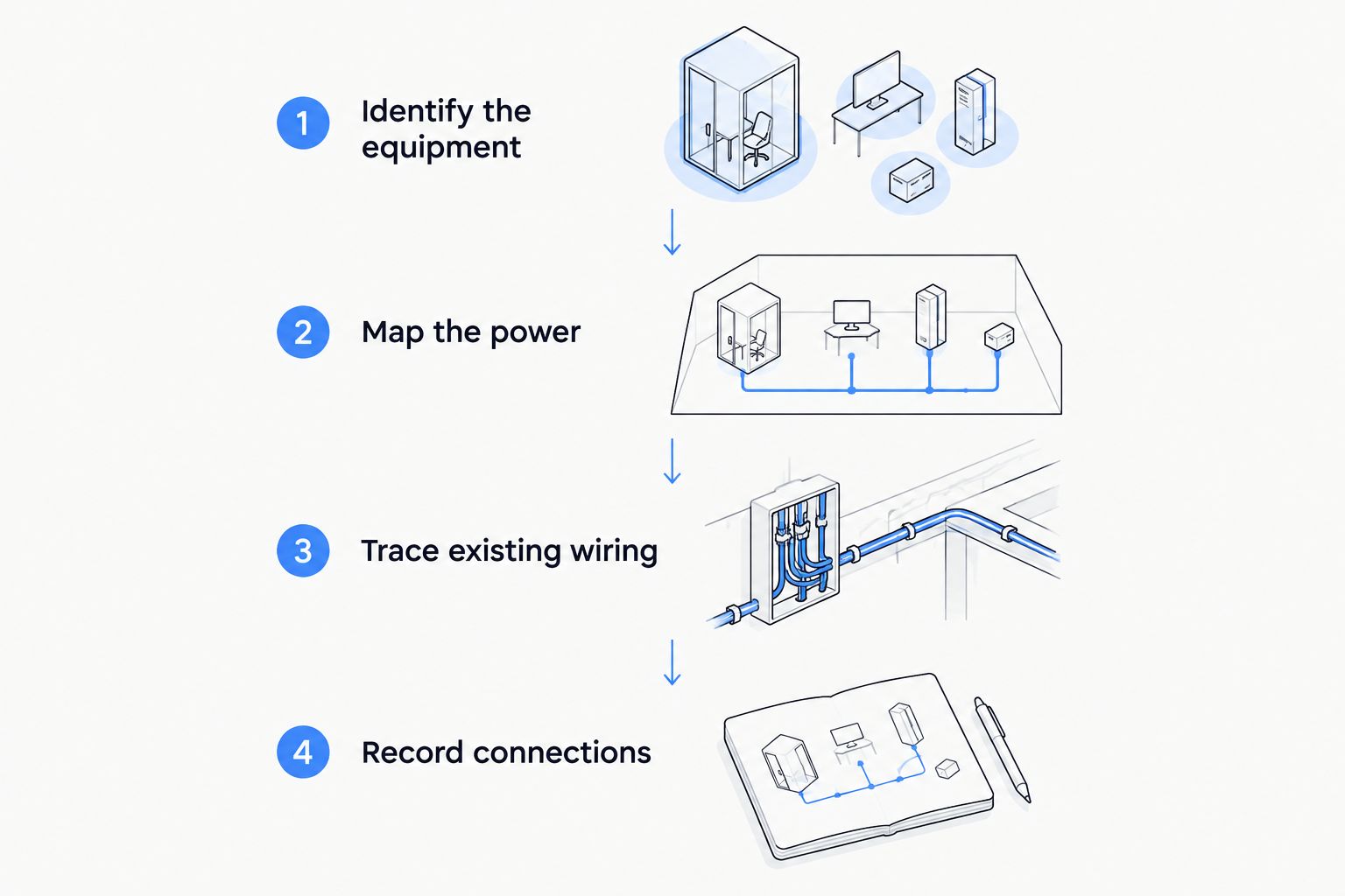
- Identify the equipment. Read the APU identification plate, controller identification, and accessory labels. Match them to the installation documents, rather than assuming all TriPac generations share connections.
- Map the power paths. Mark the battery supply and return, charging connection, controller harness, and any documented truck interface. Identify optional inverter-fed circuits separately.
- Trace the existing installation. Locate battery switches, distribution studs, protection devices, auxiliary batteries, and existing sleeper modifications. Compare the truck as wired with the drawings.
- Write a connection schedule. For each connection, record its source, destination, connector or terminal identification, protection requirement, and drawing reference. Keep this schedule with the 2026 installation record.
Use this circuit table to keep unlike connections separate:
| Circuit | Purpose | Required check | Wrong assumption to avoid |
|---|---|---|---|
| Battery supply and return | Carries APU electrical supply and return current | Approved connection points, polarity, cable specification, and protection | Any nearby stud or frame bolt is acceptable |
| Charging path | Connects charging equipment to the intended battery bank | Battery arrangement and charging compatibility | All battery banks can be connected together |
| Controller harness | Carries documented control and communication signals | Harness identity, connector assignment, and routing | Matching wire colors establish compatibility |
| Optional AC distribution | Supplies designated sleeper loads through approved equipment | Source selection, protection, grounding, and equipment instructions | A running diesel APU automatically supplies sleeper outlets |
Expected result: Every proposed connection has a documented destination. No unidentified conductor remains in the connection plan.
The connection schedule should also identify what is absent. A missing controller harness, damaged battery cable, or undocumented inverter is a stop point, not a reason to improvise a connection.
Battery cables and circuit protection
- Isolate all sources. Park securely, disable automatic starting, and disconnect electrical sources in the sequence specified by the truck and equipment manufacturers. Verify the affected circuits are de-energized with suitable test equipment.
- Confirm the battery arrangement. Check nominal voltage, polarity, battery-bank layout, and any isolation or battery-monitoring equipment. Use the approved supply and return locations; bypassing a battery-monitoring connection can interfere with its measurements.
- Install the specified conductors. Select cable construction and size from the applicable installation instructions. Account for the actual route and operating conditions rather than copying cable from another truck.
- Fit protection and supports. Install the specified fuse or breaker at the documented location. Protect cables at penetrations, support them against movement, and maintain clearance from exhaust components, sharp edges, and moving parts.
- Terminate and inspect. Use terminals and crimp tooling suited to the conductor. Tighten connections to the equipment’s specified torque, protect exposed terminals, and check routing through the cab’s applicable movement range.
Expected result: The isolated battery circuit matches the drawing, has the specified protection, and has no unsupported cable, exposed terminal, or chafe point.
Do not choose a fuse solely from an appliance’s running current. Protection must coordinate with the conductor and equipment requirements, including applicable starting loads.
For illustration, a 120 W load supplied at 12 V draws 10 A before conversion losses. That arithmetic is not a TriPac cable specification, fuse recommendation, or statement of accessory capacity.
Controller harness and sleeper distribution
- Connect the identified harnesses. Follow connector and terminal designations in the serial-specific drawing. Inspect seals, locking features, terminal retention, and previous repairs before mating connectors.
- Install documented truck interfaces only. Connect any required ignition, shutdown, or other interface exactly as specified. Do not splice into a cab control module, data network, or ignition circuit because it appears convenient.
- Route the sleeper controls. Protect the controller harness at cab penetrations and keep it away from heat and mechanical damage. Preserve the routing separation required by the installation instructions.
- Identify the outlet power source. If the truck uses an inverter or shore-power connection, follow that equipment’s distribution and transfer drawings. Keep battery conductors out of AC outlets and never backfeed a receptacle to energize the sleeper.
- Verify the intended loads. List each connected appliance and compare its electrical requirements with the documented circuit and equipment limits. Include starting demand where applicable.
Expected result: The controller and sleeper loads connect only through documented circuits. Any AC installation has an identified source and the specified distribution, protection, and transfer arrangement.
Do not invent controller settings. Use the button names, menus, and commissioning procedure in the manual for the installed controller; another generation’s interface is not a substitute.
For the 2026 handover, attach the final connection schedule and identify any sleeper circuits that remain outside APU operation. Drivers need to know which loads are supported, not simply that the APU runs.
Commissioning and load checks
- Complete the pre-power inspection. Confirm polarity, terminal protection, cable support, connector seating, and protection-device specifications. Perform de-energized checks required by the equipment instructions; never use a resistance test on an energized circuit.
- Restore power deliberately. Follow the prescribed reconnection sequence. Keep personnel clear of equipment that can start automatically, and perform running tests outdoors with exhaust directed away from occupied spaces.
- Commission the controller. Follow the model-specific startup procedure. Record displayed faults and test required shutdown or inhibit functions according to the manufacturer’s procedure; never bridge an interlock to obtain a successful start.
- Check charging under specified conditions. Measure at the locations identified in the service procedure. Compare results with the limits for the actual charging system and battery type, rather than applying a generic voltage target.
- Apply sleeper loads individually. Confirm operation, then test the intended combined load within documented limits. Check for faults, abnormal heating, voltage drop, damaged insulation, or unstable operation using the approved test method.
Expected result: The APU starts and stops correctly, charging meets the applicable specification, and intended sleeper loads operate without faults or abnormal connection heating.
Record measured values, test conditions, and instrument identification in the 2026 commissioning sheet. A no-load startup alone does not verify a completed installation.
Variant: connect an APU to a separate sleeper battery bank
A separate sleeper bank requires a different connection plan from a shared truck battery bank. Use only a charging and isolation arrangement approved for the APU, truck, and battery chemistry. Do not parallel banks simply to make the sleeper stay powered.
| Arrangement | Best for | Advantage | Limitation |
|---|---|---|---|
| Documented shared battery bank | Trucks designed around a common bank | Keeps the intended shared charging arrangement | Sleeper consumption affects the shared bank unless approved controls intervene |
| Documented separate sleeper bank | Trucks designed with isolated hotel loads | Separates sleeper loads from starting batteries as designed | Requires compatible charging, isolation, protection, and monitoring |
Have the installer identify the receiving bank, charge path, return path, and isolation behavior. Then test what happens when the APU stops and when the truck engine starts. Verify those transitions against the approved design, not against assumptions about how an isolator works.
Selecting a used TriPac assembly
Diesel Engine King lists used TriPac Evolution diesel APU take-off units. Best for: buyers sourcing a used assembly after confirming compatibility and included components. The advantage is access to a used assembly; the limitation is that the APU listing alone does not define the complete truck-side installation.
The following listings identify working or running take-off units. Neither description establishes that every harness, controller, bracket, or accessory required for your truck is included.
| Listing | Stated description | Check before selection |
|---|---|---|
| TriPac Evolution listing ending -2 | Good-used, working take-off unit | Serial number and included electrical components |
| TriPac Evolution listing ending -1 | Good-used, running take-off unit; comes as pictured | Pictured contents against the installation component list |


Troubleshooting
- Controller remains blank: Verify the documented controller supply, return, protection device, and connector seating. Test the circuit using the service procedure before replacing the controller.
- APU runs but batteries discharge: Check whether the intended bank receives charging current under the specified conditions. Inspect the charging path and assess whether connected loads exceed the system’s documented capability.
- Sleeper outlets remain dead: Identify their actual source. Check the inverter or shore-power equipment and branch protection according to its manual; APU engine operation does not prove outlet power exists.
- Protection opens repeatedly: Stop operation and isolate the circuit. Investigate shorts, damaged insulation, incorrect protection, and excessive load. Never install a larger fuse as a troubleshooting shortcut.
- Controller resets when loads start: Test supply and return voltage drop under the approved load-test conditions. Inspect battery condition and high-resistance connections before condemning electronic modules.
Customize your workflow
Build the installation into the truck’s maintenance file. Keep the diagrams, connection schedule, component identifiers, commissioning results, and driver instructions together so later repairs do not depend on tracing undocumented modifications.
For damaged or previously altered wiring, use the engine wiring harnesses guide as related background, not as a TriPac pinout. Diesel Engine King’s used truck parts catalog does not replace serial-specific installation documentation.
When adding another sleeper appliance in 2026, repeat the load review before modifying the circuit. An unused outlet does not establish unused electrical capacity.
FAQ
Can I connect a TriPac APU directly to sleeper outlets?
No. Sleeper outlets must receive power through the approved inverter or other documented AC supply and distribution equipment. Battery cables must never connect directly to AC receptacles.
What wiring diagram do I need for my TriPac installation?
Use the Thermo King installation diagram that applies to the APU’s exact model and serial number, together with the truck electrical drawings. Include separate manuals for any inverter, charger, or transfer equipment.
What cable size and fuse should I use for a TriPac APU?
Use the cable and protection specifications in the applicable installation instructions. A generic cable gauge or fuse rating cannot account for your equipment, routing, and electrical arrangement.
Can I connect the APU ground to any frame bolt?
No. Use the return connection specified by the APU and truck instructions. An arbitrary frame connection can create an unsuitable return path or bypass battery-monitoring equipment.
Why does my TriPac run while the sleeper outlets stay dead?
APU engine operation does not establish that the sleeper’s AC supply is operating. Identify the outlet source and check its inverter, transfer equipment, and branch protection using their manuals.
Can shore power and APU-related outlet power share sleeper circuits?
They can share designated circuits only through an approved source-selection arrangement. Never connect competing AC sources together or backfeed the sleeper through a receptacle.
Does buying a used APU include everything needed for installation?
Do not assume a used APU includes every truck-side component. Compare the listing contents with the serial-specific component list and confirm harnesses, controller, mounting hardware, and accessories separately.
One last thing
Keep the removed harness labels until commissioning is complete. Photograph connector locations before disassembly, then retain those photographs with the final drawings. A unit that runs on the donor truck is not proof that its connections belong in the same locations on the receiving truck.

