


How to connect a Jake brake to a Cummins or Detroit Diesel engine
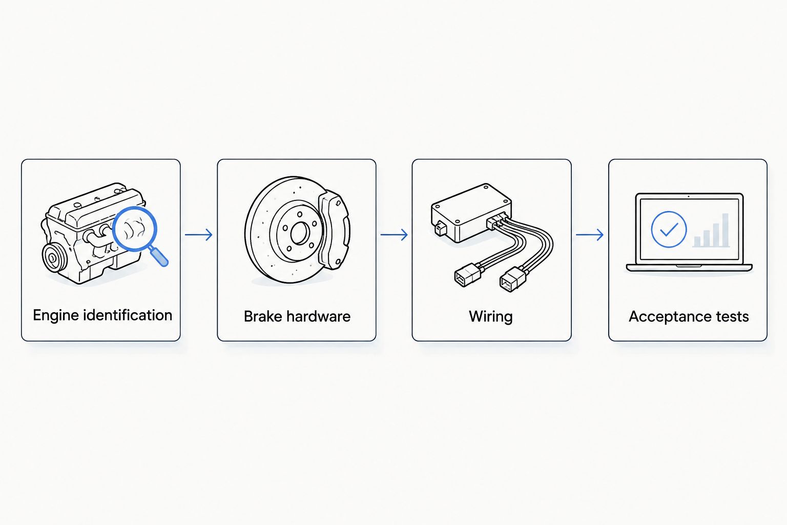
Instead of tracing loose wires and guessing which switch controls the retarder, connect a Jake brake to a Cummins or Detroit Diesel engine by matching the brake hardware, engine wiring, control logic, and adjustment procedure to the exact engine serial number. Use the workflow below to organize the installation; a qualified diesel technician must complete the engine-specific mechanical work, electrical connections, and acceptance tests.
- To connect jake brake to cummins or detroit diesel engine hardware, identify the exact engine and brake first.
- Cummins and Detroit Diesel installations require engine-specific wiring, adjustments, and control settings—not a universal connection diagram.
- Diesel Engine King serves used commercial truck engine and parts buyers; confirm brake compatibility separately.
- Never bypass clutch, accelerator, transmission, or other required engine-brake interlocks.
Why this matters
A compression-release engine brake changes exhaust-valve operation during engine braking. It is not simply an accessory connected to a dashboard switch, and it is not the same mechanism as an exhaust restriction brake.
The installation has to match both the engine and the truck. Correct brake housings do not establish that the harness, controller configuration, or driver controls are correct. Start with the Jake brake parts for Cummins and Detroit Diesel engines guide when organizing the parts identification.
Diesel Engine King is for commercial truck buyers sourcing used diesel engines and heavy truck parts. That parts-buying role does not establish that any particular engine includes a compatible brake assembly, complete wiring, or the configuration your truck needs.
For a 2026 installation, use service information applicable to the engine's actual build and installed components. The current calendar year does not change the specifications of an older engine.
Before you start
- Identification and documents: Record the engine serial number, truck VIN, brake assembly identification, and controller identification—4 identification records for the job file. Obtain the applicable engine-brake installation instructions, engine service procedure, and truck wiring diagram.
- Access and equipment: Arrange a qualified diesel technician, safe workshop access, approved lifting equipment where required, calibrated adjustment tools, electrical test equipment, and the diagnostic access required by the installed control system. Secure the truck and follow the manufacturer's isolation procedure before opening connectors or removing covers.
- Compatibility gate: Establish whether you are reconnecting factory-installed hardware or installing a brake that the engine did not previously have. A matching connector or engine-family name does not prove compatibility; internal hardware, oil passages, harness circuits, and electronic configuration must match the approved application.
Do not start disassembly until the correct adjustment procedure and wiring diagram are identified. Pin assignments, fastener torque, brake clearance, supply voltage, and test limits belong to the specific installation—not a generic internet diagram.
Engine identification and installation route
- Read the engine identification directly from the engine and compare it with the truck records. Identify any replacement engine or previous repower before selecting instructions.
- Read the identification on the installed brake hardware. Establish whether the assembly is complete, partially removed, or absent.
- Identify the control system and transmission application. Determine from the truck diagram whether brake requests use discrete wiring, electronic communication, or a combination.
- Open a 2026 installation record containing the applicable document revisions, component identification, and unresolved compatibility questions. Resolve those questions before ordering parts.
Expected result: You have an approved installation route tied to the actual engine, brake assembly, and chassis—not merely a Cummins or Detroit badge.
Cummins versus Detroit Diesel: what changes?
Neither engine brand has a single universal Jake brake connection. Use this comparison to select the documentation route, not to select pin numbers or adjustment values.
| Installation route | Best for | Advantage | Limitation |
|---|---|---|---|
| Cummins engine-specific procedure | A confirmed Cummins engine and approved brake application | Ties parts and adjustments to the identified engine | A different Cummins family or build can require different hardware and controls |
| Detroit Diesel engine-specific procedure | A confirmed Detroit engine and approved brake application | Ties the brake installation to the identified Detroit engine and control system | Series 60 instructions are not interchangeable with DD-series instructions |
| Existing factory-system reconnection | A truck retaining its approved original brake equipment | Preserves the established chassis control arrangement | Previous wiring changes and replacement components still require verification |
For Cummins applications, use the engine serial number and applicable parts information, including the CPL where relevant. For Detroit Diesel applications, identify the engine family, serial number, and installed control generation. Do not transfer a connection method between engine families because the dashboard switches look alike.
Brake hardware and mechanical adjustment
- Isolate the truck as directed by the service procedure. Clean the work area before opening the valve-cover area, and prevent debris from entering the engine.
- Inspect the brake assemblies, mounting points, electrical feedthroughs, seals, and associated valve-train components. Compare what is present with the approved parts list; do not treat a collection of used components as a complete kit.
- Have the technician install or reconnect the mechanical components in the specified sequence. Verify the required oil supply arrangements, correct fasteners, and any application-specific supporting components.
- Set the valve train and engine brake using the exact crankshaft positions, temperature conditions, measuring tools, and clearances in the applicable procedure. Record the specified values and measured results.
- Complete the manufacturer's mechanical checks before closing the engine. Account for tools and loose parts, inspect routing, and install covers and seals correctly.
Expected result: The brake hardware is mechanically compatible, correctly secured, and adjusted to the documented specification.
Do not use an adjustment value copied from a different engine or brake model. Incorrect clearance or assembly can damage the valve train. Stop if identification is missing, a mounting feature differs, or the specified adjustment cannot be obtained.
A used assembly deserves the same inspection and adjustment checks as any replacement part. Appearance alone does not establish serviceability, and an electrical click does not confirm correct mechanical operation.
Wiring and control configuration
- Trace the approved control path on the truck and engine diagrams before making connections. Identify the driver request, controller inputs, actuator outputs, protective devices, connectors, and return paths that apply.
- Compare connector cavity identification and wire functions against the diagram. Inspect for corrosion, spread terminals, damaged insulation, oil intrusion, and earlier repairs. Repair defects using the specified terminals, seals, and methods.
- Connect the brake harness through the approved connectors and routing points. Secure it away from hot surfaces, moving parts, sharp edges, and cover pinch points. Do not identify a circuit by wire color alone.
- Connect the required driver controls and interlocks according to the chassis diagram. Verify accelerator status, clutch status where applicable, transmission conditions, and other specified enable or inhibit inputs.
- On electronically controlled applications, use the manufacturer-supported diagnostic procedure to verify the installed brake configuration and control inputs. Use the actual software labels and service instructions for that controller; do not substitute settings from another engine.
- Perform the specified circuit checks before commanding operation. Do not apply battery power or ground to an unidentified pin, and do not use a jumper to defeat a control input.
Expected result: The driver request reaches the correct control system, required interlocks report correctly, and the approved output circuits pass their specified checks.
Think of the connection as a chain of separate checks. Hardware compatibility comes first; a dashboard switch cannot correct an incompatible brake assembly or missing oil-supply provision.
Do not replace an engine controller simply because the engine brake does not respond. First distinguish a missing request, an active inhibit condition, an output-circuit fault, and a mechanical fault. Each requires a different repair.
Acceptance tests and handover
- Restore power only after completing the mechanical and electrical inspections. Check for leaks, warning indications, and relevant faults using the applicable procedure.
- Verify switch requests and required interlock states with the prescribed test method. Confirm that the system recognizes both the enable condition and each required cancellation condition.
- Run only the stationary checks authorized for that engine. Do not expect normal braking performance while parked, and do not operate exposed moving valve-train components without the manufacturer's approved procedure and protection.
- Have a qualified driver and technician perform the prescribed operational test in a controlled, suitable area. Check the supported brake selections and cancellation behavior without exceeding engine or vehicle limits.
- Save the results in the 2026 job file. Record faults found, repairs completed, final configuration, and acceptance criteria satisfied before returning the truck to service.
Expected result: The engine brake responds only under the intended conditions, cancels when required, and passes the manufacturer's acceptance procedure.
Plan 2 test phases: workshop verification and controlled operational verification. Neither replaces the other. A circuit that passes an electrical check still needs a functional test, while a brief braking response does not prove that every safety interlock works.
An engine brake supplements the service brakes; it does not replace them. Follow the truck operator's instructions for traction conditions, engine speed, and permitted use.
Reconnect a Jake brake after an engine replacement
An engine replacement creates a separate workflow: preserve the approved chassis controls while confirming that the replacement engine supports them. Do not assume the donor engine's brake equipment and calibration match the receiving truck.
Use 3 compatibility checks before transferring connections:
- Mechanical match: Compare the replacement engine's brake hardware and supporting components with the approved application.
- Electrical match: Compare connectors, circuit functions, harness routing, and required inputs with the receiving truck's diagrams.
- Configuration match: Confirm that the installed controllers and software configuration support the intended engine-brake operation and transmission integration.
Photograph and label connections before removal, then verify each against the correct documentation during installation. Photographs preserve the previous arrangement; they do not prove that arrangement was correct.
For a 2026 repower, retain the original and replacement identification records together. Diesel Engine King buyers sourcing used diesel engines and heavy truck parts should separate included components from components that need inspection, transfer, or replacement.
Troubleshooting
No response from any brake selection
Check whether the system receives the driver request and whether an inhibit condition is active. If the request is missing, diagnose the switch and input path; if the request is present, follow the controller's enable-condition and output-circuit tests. Do not bypass the clutch or accelerator input to force operation.
Only part of the brake operates
Compare the selected stage with the commanded outputs using the application-specific procedure. Inspect the affected circuit, connectors, actuator, and mechanical assembly in the order specified. Do not assume every engine divides braking stages into the same cylinder groups.
The brake operates but braking is weak
Verify the operating conditions before adjusting anything. Then check applicable faults, oil-related requirements, mechanical adjustment, and component condition using the service procedure. Do not change clearance to increase braking strength.
The brake fails to cancel or operates unexpectedly
Remove the truck from service until the fault is corrected. Diagnose the driver request, accelerator and clutch inputs where fitted, wiring faults, and controller behavior. Unexpected operation is not a condition to work around with a different driving technique.
Customize your workflow
Build a reusable inspection sheet around the installation route, not a universal pinout. Include identification, document revisions, mechanical measurements, circuit results, control-input checks, and the final acceptance record.
Keep the 2026 completion date separate from the engine's build information. That distinction helps the next technician locate the correct specifications without mistaking a recent installation for a newer engine design.
When sourcing from Diesel Engine King, identify the engine and the required component before comparing used parts. A replacement module, harness, or brake assembly is a repair decision only after diagnosis establishes what failed.
FAQ
Can I connect a Jake brake directly to a dashboard switch?
Only use the connection arrangement specified for the exact engine and chassis. Do not directly energize a brake actuator unless the approved wiring and test procedure explicitly requires it; required controls and interlocks must remain functional.
Is Jake brake wiring the same on Cummins and Detroit Diesel engines?
No. Cummins and Detroit Diesel installations use application-specific hardware, wiring, adjustments, and controls. Identify the engine serial number and brake assembly before selecting instructions.
Can I add a Jake brake to an engine that never had one?
Installation requires confirmation that the exact engine supports an approved engine-brake application. A switch and wiring alone do not establish compatibility; the required mechanical components and control arrangements must also be present.
Do I need to program the ECM after connecting an engine brake?
Programming requirements depend on the installed control system and existing configuration. Follow the manufacturer-supported procedure to verify configuration rather than assuming every installation needs a software change.
What Jake brake clearance should I use?
Use the clearance specified for the exact engine and brake model under the stated adjustment conditions. There is no universal clearance that applies to all Cummins and Detroit Diesel engines.
Why does my Jake brake stop working when I press the clutch?
Clutch operation cancels engine braking on applications designed with that interlock. Verify the expected behavior in the truck's operating and service instructions; never bypass the switch to keep the brake engaged.
Can I test a Jake brake while the truck is parked?
Perform only the stationary checks authorized by the manufacturer. Stationary input or circuit checks do not replace the prescribed controlled operational test.
One last thing
Test cancellation as deliberately as engagement. A brake that turns on has passed only part of the job; the handover record must also show that it stops operating under every required cancellation condition.

