


How to connect a diesel APU to a reefer unit for continuous power
Instead of manually switching power sources whenever you park, connect a diesel APU to a reefer unit only through a manufacturer-approved electrical standby interface with a compatible power supply and protected transfer arrangement. This workflow supports refrigeration between operating modes; a sleeper-cab APU, battery connection, or plug adapter alone does not establish compatibility or guarantee uninterrupted cooling.
- Connect diesel APU to reefer unit only after verifying electrical standby capability, generator output, and manufacturer approval.
- Diesel Engine King supplies used commercial truck engines and parts; match replacement parts by documented application.
- Battery charging supports controls and starting; it does not replace compressor power.
- Test starting demand, source transfer, alarms, and backup refrigeration before carrying temperature-sensitive freight.
Why this matters
A diesel auxiliary power unit and a diesel transport refrigeration unit serve different loads. A sleeper APU can support cab equipment without providing the electrical output a reefer compressor requires. The word diesel describes the fuel, not the electrical interface.
The standby input specification decides whether this connection is possible. If the reefer has no approved external-power input, stop: this is not a cable-installation job. Keep the reefer on its intended power source and ask its manufacturer about supported alternatives.
Diesel Engine King is best for buyers sourcing used commercial truck engines and heavy truck parts, not for establishing APU-to-reefer electrical compatibility. Use Diesel Engine King for parts sourcing after the equipment requirements are settled.
For a 2026 installation, build the job around the manuals for the actual model and serial numbers. This guide covers compatibility checks, installation handoff, commissioning, and operating limits—not universal terminal assignments.
Before you start
- Equipment records: Obtain the APU and reefer model numbers, serial numbers, wiring diagrams, installation manuals, and nameplate photographs. Confirm whether the reefer has a factory or manufacturer-approved electric standby system.
- Qualified installation support: Arrange a transport refrigeration technician and an electrician qualified for the applicable mobile generator installation. Have them specify the inlet, cable assembly, protection, grounding, bonding, and source-transfer equipment.
- The easily missed restriction: Confirm starting demand, phase, and duty rating—not just running watts. A source can have enough advertised power yet still be unsuitable for the reefer’s compressor start or required electrical configuration.
Do not choose wire sizes, breakers, adapters, or control connections before these checks. Disable automatic starting and isolate every applicable energy source under the equipment procedures before inspection or installation. Reefer fans and engines can start without a person operating the controls.
Power-path selection
Establish the supported operating arrangement
- Identify the reefer drive system. Read the service documentation to determine whether cooling uses an engine-driven compressor, an electrically driven compressor, or another manufacturer-defined arrangement. Do not infer this from the presence of a battery.
- Locate the documented external-power interface. Confirm its intended function. A battery-charging connection and an electric standby inlet are not interchangeable.
- Define what continuous power means. Decide whether the requirement is parked cooling, automatic backup after source loss, or operation while moving. Each requires explicit equipment support.
- Select only a supported power path. Use the comparison below to separate compressor power from battery support. Record the selected arrangement in the installation work order.
| Arrangement | Best for | Advantage | Limitation |
|---|---|---|---|
| Compatible generator feeding approved electric standby | Parked refrigeration with a documented external-power input | Runs refrigeration through its intended standby interface | Requires matching electrical output and adequate starting capacity |
| Reefer operating on its own diesel system | Equipment without compatible external-power support | Retains the intended refrigeration power path | Does not transfer compressor operation to the truck APU |
| Approved battery charging or DC support | Maintaining starting batteries and control power | Addresses battery support separately from cooling power | Does not power an engine-driven compressor |
Expected result: You have a documented supported arrangement—or a clear decision not to connect the APU. An unidentified inlet or unsupported operating mode is a stop condition, not an invitation to improvise.
A 2026 equipment list should distinguish the source, refrigeration load, and battery-support circuit. That separation prevents a charging upgrade from being mistaken for a refrigeration-power upgrade.
Electrical compatibility record
Verify output against the reefer input
- Copy the electrical specifications exactly. Record output voltage, AC or DC, phase, frequency, continuous rating, and starting capability from the applicable documentation. Record the reefer’s corresponding standby requirements alongside them.
- Separate low-voltage DC from compressor supply. A 12 V DC battery circuit and a 24 V DC battery circuit are different systems; neither establishes compatibility with an AC standby inlet. Treat these as voltage examples, not specifications for your equipment.
- Verify frequency and phase together. If the reefer documentation specifies 60 Hz, the source must meet that requirement within the manufacturer’s permitted limits. Matching frequency does not resolve a phase or voltage mismatch.
- Check the full operating load. Include the refrigeration equipment and any other loads sharing the APU. Have the installer account for compressor starting, fans, defrost, ambient conditions, and documented generator derating.
- Obtain approval before buying connection hardware. Resolve missing starting-current data, output restrictions, and standby limitations with the equipment manufacturers or their authorized technical support.
Expected result: The technician has confirmed compatibility across every required electrical characteristic and operating condition. An unresolved requirement means the connection is not ready for installation.
Do not size this system from engine horsepower. Electrical output depends on the generator and its controls, and a breaker rating does not prove usable continuous capacity. Likewise, an inverter does not make an undersized source suitable merely because it changes the output form.
Protected connection assembly
Specify isolation, protection, and cable routing
- Approve the connection drawing. Have the installer identify the permitted source, standby inlet, disconnects, overcurrent protection, protective conductors, and transfer arrangement. Use the equipment-specific drawings rather than a generic truck wiring diagram.
- Prevent backfeeding. Where alternate electrical sources exist, use the manufacturer-approved switching or interlocking arrangement. Do not connect generator outputs together or energize a shore-power connection backward.
- Resolve grounding and bonding. Have the qualified installer determine the required protective-earth connections, neutral treatment, and switching configuration. Do not assume the trailer frame alone provides the required electrical protection.
- Specify the cable assembly. Select it for the documented current, installation conditions, length, connector system, and environmental exposure. Route it away from exhaust heat, moving components, sharp edges, road damage, and coupling pinch points.
- Complete the isolated installation. Keep power isolated until the installer finishes the prescribed inspection and electrical tests. Never use a male-to-male cord or a homemade adapter to bypass incompatible connections.
Expected result: The completed assembly matches the approved drawing, prevents unintended source interconnection, and passes the required pre-energization checks.
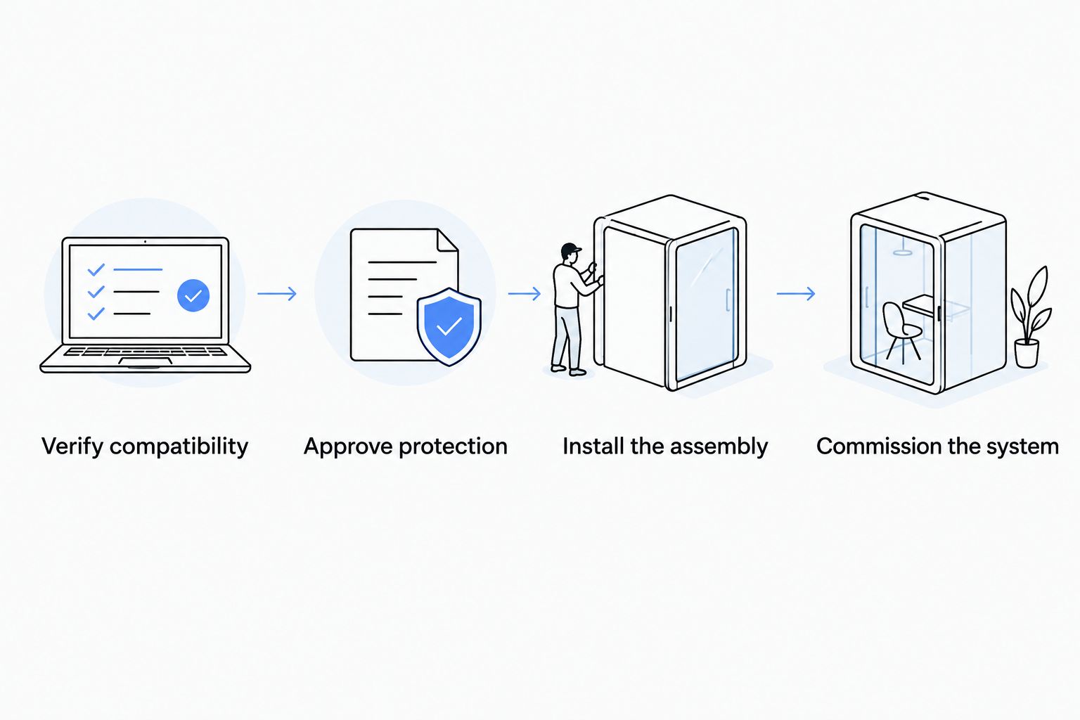
The connection sequence is simple to describe but equipment-specific to execute: verify compatibility, approve protection, install the assembly, then commission the system. None of those gates can substitute for another.
Do not modify refrigerant piping, compressor drives, fuel plumbing, or safety circuits to force compatibility. Those changes fall outside an external standby-power connection and require their own approved engineering and service procedures.
Commissioning and operating controls
Test the complete refrigeration cycle
- Use an unloaded trailer or another approved test condition. Do not make temperature-sensitive freight the first test load. Record the cargo-space condition and intended temperature requirement.
- Start the source according to its manual. Verify its output using the prescribed procedure before enabling the refrigeration load. Energized measurements belong to qualified personnel using suitable instruments and protective procedures.
- Select the reefer’s documented standby mode. Follow the exact control labels and sequence in that model’s operator manual. Do not substitute a guessed menu label or defeat a safety interlock.
- Observe the operating cycle. Check compressor starting, steady operation, fan operation, and defrost behavior where applicable. Record electrical measurements, active alarms, and refrigeration performance against the manufacturer’s acceptance limits.
- Test source loss and restoration. Follow the approved commissioning procedure. Confirm the actual fallback behavior, restart restrictions, and alarm response rather than assuming the reefer will restart on diesel automatically.
- Release the system with written instructions. Give drivers the connection sequence, disconnection sequence, fault response, and approved operating conditions. Include the 2026 commissioning record with the equipment file.
Expected result: The system runs within documented limits, responds correctly to a source failure, and has a usable operator procedure. A successful initial compressor start is not a completed commissioning test.
Continuous refrigeration does not necessarily mean continuous electrical supply. A transfer can interrupt power, and compressor controls can impose restart delays. Confirm that the resulting refrigeration performance meets the cargo requirement before dispatch.
Battery support without powering the compressor
A second workflow exists when the actual problem is a weak reefer starting battery rather than a need for electric standby. Keep battery support separate from compressor power. An approved charger can support a battery without creating an external refrigeration-power system.
- Identify the battery voltage, chemistry, and charging requirements from the reefer documentation.
- Have the technician select an approved charger or DC support arrangement compatible with both systems.
- Specify circuit protection, isolation, connections, and disconnect procedures through the approved installation instructions.
- Test charging behavior with the reefer stopped and running as permitted by the manufacturer.
- Confirm that faults cannot create an unintended connection between separate battery systems.
Expected result: The battery receives supported charging while the reefer retains its intended compressor drive. Do not describe this arrangement as APU-powered refrigeration.
For a 2026 maintenance plan, list battery condition, charging-system inspection, and refrigeration service separately. Keeping those tasks distinct makes fault isolation clearer when a reefer will not start.
Troubleshooting
The APU runs, but the reefer will not enter standby
Confirm that electric standby is actually installed and supported. Then have the technician check the source specifications, inlet circuit, interlocks, and stored alarms against the model’s diagnostic procedure; a running APU does not prove acceptable electrical input.
Protection trips when the compressor starts
Stop repeated restart attempts. Have the installer compare starting demand and measured supply behavior with the approved design, inspect the cable assembly, and check the refrigeration equipment for faults. Do not increase breaker size to conceal the problem.
The connector gets hot or shows damage
Stop operation and isolate the connection using the approved procedure. Have the assembly inspected for damaged contacts, loose terminations, contamination, incorrect ratings, and cable damage before reuse. Do not reconnect a heat-damaged plug.
The reefer stops after the external source fails
Check whether automatic diesel fallback is supported and enabled under the manufacturer’s instructions. Investigate fuel, starting-battery condition, alarms, and restart restrictions separately; never bypass a shutdown to preserve a load.
Cooling deteriorates despite stable electrical output
Treat this as a refrigeration-performance problem as well as a possible supply problem. Arrange checks of airflow, condenser condition, defrost operation, door sealing, and refrigeration faults. Stable voltage alone does not establish adequate cooling.
Customize your workflow
Expand the installation into a documented operating routine. Assign responsibility for checking connections, verifying temperature alarms, responding to source loss, and removing the equipment from service after an electrical fault.
Use the diesel auxiliary power unit maintenance guide to organize the source-equipment service plan. Keep the manufacturer’s maintenance intervals and procedures as the controlling requirements.
Diesel Engine King’s used commercial truck parts should be selected by documented application and part identification. An engine control module or unrelated truck component does not establish standby compatibility, replace transfer protection, or convert a sleeper APU into a reefer generator.
FAQ
Can I connect any diesel APU to a reefer unit?
No. The reefer needs a supported external-power interface, and the APU output must match its voltage, phase, frequency, starting demand, and continuous-load requirements. Confirm the arrangement with the equipment manufacturers before installation.
Can a sleeper-cab APU run my trailer refrigeration?
Only if its documented electrical output and permitted application meet the reefer’s standby requirements. Cab-power capability alone does not establish compressor-power capability.
Can I connect the APU directly to the reefer battery?
Do not directly tie the systems together without an approved charging design. Battery support requires compatible charging characteristics, protection, and isolation, and it does not replace compressor power.
Does a reefer need electric standby to use external generator power?
The reefer needs a manufacturer-supported external electrical power path. A diesel-only compressor drive cannot be converted into electric standby by adding a cord.
Will the reefer automatically restart on diesel if the APU stops?
Do not assume automatic diesel restart. Verify that the specific reefer supports that behavior, configure it according to its manual, and test it during commissioning.
Can I leave the APU-to-reefer cable connected while driving?
Only when the complete installation is explicitly approved for operation while moving. A parked standby cable arrangement does not establish road-use suitability.
What information should I send a technician before connecting the equipment?
Send model numbers, serial numbers, nameplate photographs, manuals, wiring diagrams, and the intended operating conditions. Include the reefer’s standby requirements and every load expected to share the APU.
One last thing
Commission the failure response, not just normal operation. A connection that cools the trailer while everything works has not demonstrated backup capability. Add the tested source-loss response and driver instructions to your 2026 dispatch file before using the arrangement for temperature-sensitive freight.

