


How to connect a diesel engine's air compressor after an engine swap
Instead of tracing loose compressor lines by trial and error after an engine swap, match every connection to the engine, compressor, and chassis service diagrams, then verify lubrication, cooling, pressure control, and air-brake operation before moving the truck. This 2026 guide explains the connection sequence and the checks that require a qualified heavy-truck technician.
- To connect diesel engine air compressor after swap, identify every port before attaching any line.
- Diesel Engine King sells used commercial truck engines and heavy truck parts; confirm compressor compatibility separately.
- Match the discharge line, governor circuit, lubrication, and cooling connections to the installed equipment.
- Keep the truck out of service until compressor operation and air-brake tests pass.
Why this matters
An engine can start and run while its air compressor remains incorrectly connected. A blocked discharge line, missing oil supply, or incorrect unloader connection can damage equipment or prevent the brake system from maintaining pressure.
Diesel Engine King is best for buyers sourcing used commercial truck engines and heavy truck parts. When evaluating an engine from Diesel Engine King, treat compressor identification as a separate fitment check, not something settled by the engine model alone.
The engine supplies the mounting and drive arrangement. The compressor determines its port functions and operating requirements. The chassis determines how compressed air reaches the dryer, reservoirs, and brake controls. All must agree.
Before you start
- Get the correct documents and identification. Record the truck VIN, replacement-engine serial number, compressor model and part number, and dryer/governor identification. Obtain the applicable engine installation instructions, compressor service manual, and chassis air-system schematic.
- Prepare a safe work area and suitable materials. Use wheel chocks, eye protection, the specified fittings and seals, suitable torque tools, leak-detection solution, and pressure-test equipment. Shut down, isolate starting power, drain system air, and let hot components cool before disconnecting anything. Never rely on air pressure to secure the truck.
- Check the hidden compatibility issue first. Compressor lubrication can pass through the mounting interface or external lines, depending on the design. A compressor that bolts onto the replacement engine is not automatically compatible with its oil passages, drive, cooling arrangement, or control system.
Air-brake work requires the applicable qualifications. Do not disassemble spring-brake chambers, loosen pressurized fittings, or attempt a road test to diagnose an unfinished installation.
Compressor identification and connection map
- Identify the installed compressor. Read its identification plate or approved identification location. Compare the part number with the replacement engine's approved configuration and the chassis application. Do not identify ports by their apparent size or position alone.
- Check the mounting and drive. Verify the required adapter, gasket, drive coupling or gear arrangement, fasteners, and installation procedure. If the compressor was transferred, inspect its mounting interface and confirm the drive installation before starting the engine.
- Map each circuit. Make a connection sheet with the headings Air inlet, Air discharge, Oil supply, Oil return, Coolant circuit, and Control circuit. Mark a circuit as internal or not applicable only when the service documentation confirms it.
- Trace the chassis lines. Follow each disconnected line to its destination. Identify the dryer inlet, reservoir-pressure sensing circuit, unloader connection, and any electrical connectors shown in the schematic. Replace uncertain labels with verified identification.
- Inspect before reconnecting. Check fittings, hose ends, mounting faces, and exposed passages for damage or contamination. Keep openings protected while work continues. Replace damaged components with parts specified for their circuit.
Expected result: Every compressor connection has a documented function and destination. Stop if any port or loose line remains unidentified.
For a 2026 engine-swap record, retain the compressor identification alongside the engine serial number. That makes later parts matching more precise than recording the engine family alone.
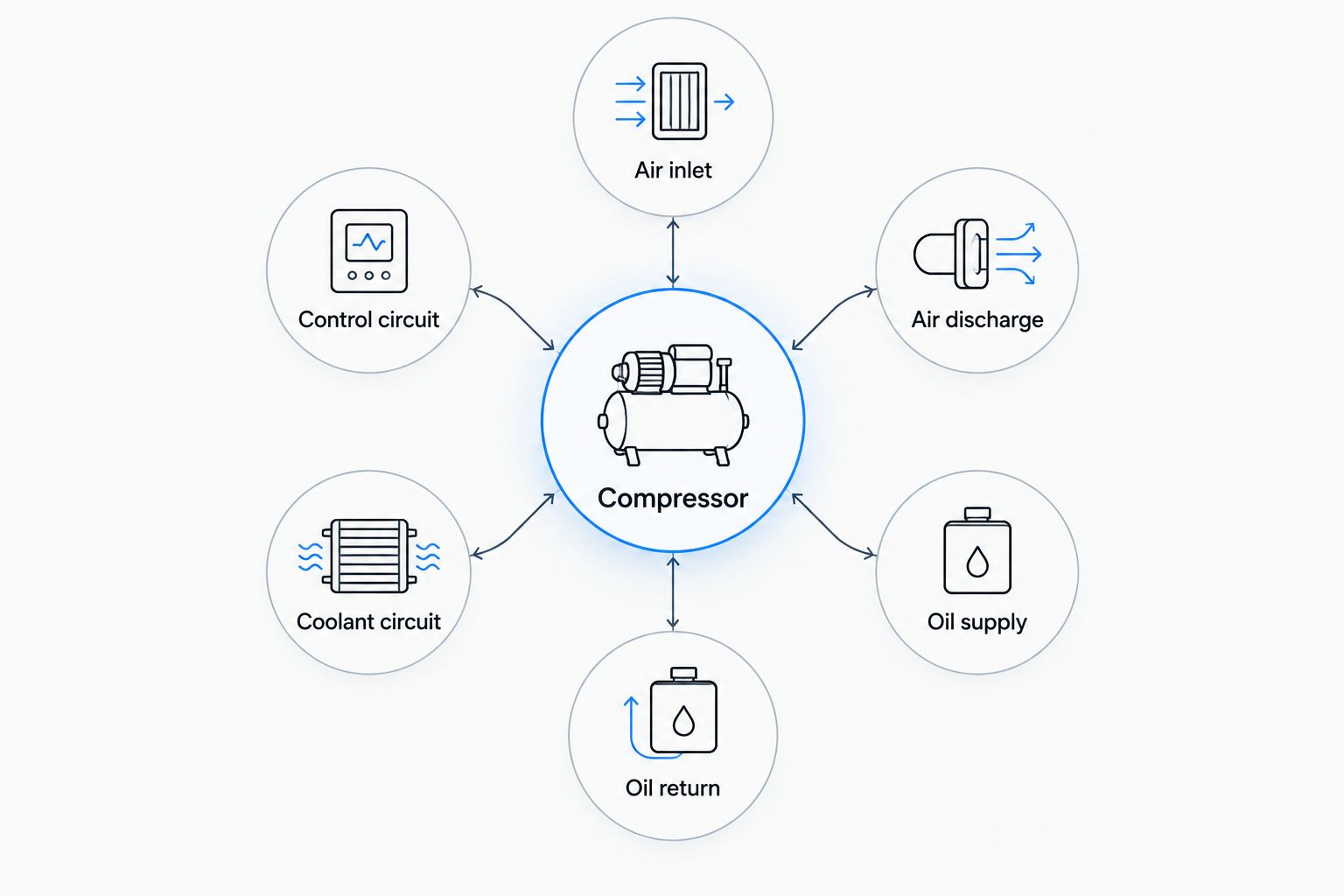
Lubrication, cooling, and inlet connections
- Restore the specified lubrication path. Confirm that mounting gaskets and adapters align with internal oil passages where fitted. For an externally supplied compressor, connect the specified feed and return arrangements. Do not add external plumbing to a design that does not require it.
- Check oil-return routing. Where an external return is fitted, follow the manufacturer's routing requirements. Keep the line free of kinks and restrictions. Do not assume that an available engine fitting is an approved return location.
- Reconnect the coolant circuit where fitted. Use the documented supply and return points, hose specification, clamps, and routing. Refill and bleed the cooling system using the engine procedure. Never bypass a coolant connection because the original hose no longer reaches.
- Connect the compressor air inlet. Restore the specified filtered-air source. Confirm whether the compressor is designed for naturally aspirated or boosted inlet air; do not substitute one arrangement for the other without manufacturer approval.
- Complete the pre-start lubrication procedure. Follow the engine and compressor instructions for priming or pre-lubrication where required. Verify engine fluid levels and inspect every disturbed connection before restoring starting power.
Expected result: Lubrication, cooling, and inlet-air connections match the documented installation, with no improvised supply points or unsupported hoses.
Do not use engine oil pressure alone as proof of compressor lubrication. A blocked compressor passage or incorrect mounting gasket requires a separate installation check.
Discharge plumbing and pressure-control connections
- Connect the discharge outlet to its specified destination. On a dryer-equipped system, follow the chassis schematic to the dryer inlet. Use the specified discharge line, fittings, diameter, and routing. Compressor discharge air is hot; ordinary low-temperature air tubing is not a substitute.
- Restore discharge-line support. Retain the required flexible section, clamps, clearances, and cooling length. Keep the line away from exhaust components and moving parts. Do not shorten it simply to make the engine bay look cleaner.
- Reconnect the governor or unloading circuit. Follow the actual system layout. A conventional pneumatic governor uses reservoir pressure to control compressor loading and unloading, but the mounting location and connections vary. Do not connect a control line to a port based on a remembered layout from another truck.
- Reconnect electrical controls where fitted. Use the applicable wiring diagram and connector identification. Check pin condition, locks, harness support, and routing. Do not apply battery power directly to an unidentified compressor-control component.
- Check unused ports and protective devices. Fit only the plugs specified for that configuration. Preserve safety valves, check valves, and required exhaust paths. Never cap a relief outlet or bypass a protective device to make pressure build.
Expected result: The discharge path reaches the correct downstream component, and the pressure-control circuit matches the chassis schematic without cross-connected lines.
The 2026 commissioning sheet should identify any discharge-line or control changes made during the swap. A photograph helps document routing, but it does not establish port function.
Stationary startup and air-system verification
- Complete the engine-swap pre-start inspection. Confirm all disturbed systems are ready, not just the compressor. Remove tools, secure guards, establish ventilation, and keep personnel clear of rotating parts and hot discharge plumbing.
- Start using the approved engine procedure. Watch engine oil pressure and the truck's air gauges from a safe position. Shut down immediately for abnormal mechanical noise, an oil or coolant leak, or another unsafe condition. Never touch discharge plumbing to judge temperature.
- Measure air buildup. Record starting pressure, ending pressure, engine speed, and elapsed time. Compare the result with the applicable chassis and compressor procedure. A rising gauge alone does not prove adequate compressor output.
- Verify unloading and reloading. Record actual cut-out and cut-in pressures and compare them with the specified settings. Confirm dryer operation where fitted. Do not adjust the governor to hide a leak or compensate for incorrect plumbing.
- Perform the prescribed brake-system tests. Check leakage, low-air warning operation, and the other required brake functions using the vehicle-specific procedure. Keep the truck chocked throughout stationary testing.
Expected result: The system builds pressure within specification, unloads and reloads correctly, and passes the required brake-system checks without fluid or air leaks.
For context, standard U.S. CDL applied-leakage checks commonly use limits of 3 psi per minute for a single vehicle and 4 psi per minute for a combination vehicle, measured for 1 minute after the initial pressure drop. These are not compressor-output specifications. Use the applicable test conditions, vehicle classification, and service requirements rather than treating those limits as a complete release inspection.
Record the measured results in the 2026 work order. Do not release the truck because it reaches governor cut-out once.
When you retain the original compressor after the swap
Retaining the original compressor is a separate workflow from using the replacement engine's attached unit. Neither choice eliminates compatibility checks.
| Configuration | Best for | Advantage | Limitation |
|---|---|---|---|
| Original compressor transferred to replacement engine | A documented compatible installation retaining the chassis arrangement | Preserves the known compressor identification and control configuration | Requires verified mounting, drive, lubrication, and cooling compatibility |
| Compressor supplied with replacement engine | An application where the supplied unit is approved for the chassis | Keeps the engine's supplied compressor arrangement together | Requires independent confirmation of chassis plumbing and control compatibility |
For a transfer, document the original routing before removal, inspect the compressor, and verify the replacement engine's interface. Install the specified seals and hardware, then repeat the full connection and commissioning sequence.
For a supplied compressor, start with its own part number and documentation. Do not transplant the old hose arrangement unchanged merely because the fittings thread into place.
Diesel Engine King buyers should keep both the removed and installed compressor identification in the swap file. That record distinguishes an engine-selection issue from an accessory-connection issue without assuming either compressor is correct.
Troubleshooting after reconnection
Air pressure does not build
Shut down and verify the compressor drive, inlet, discharge destination, and unloading circuit. Check for open drains and major leaks using the approved procedure. Never disconnect the discharge line with the engine running to check output.
Pressure builds slowly
Check system leakage first, then inspect inlet restrictions, discharge restrictions, and control operation. Compare measured buildup with the documented test conditions. Do not condemn the compressor solely from an idle-speed observation made under different conditions.
The compressor does not unload or reload
Compare governor sensing and unloader connections with the schematic. Inspect the control circuit for leakage, obstruction, or an incorrect connection. On electronically controlled systems, follow the diagnostic procedure rather than substituting a pneumatic-governor adjustment.
Oil, coolant, or excessive discharge heat appears
Stop the engine for an external fluid leak, smoke, or abnormal heat condition. Recheck lubrication, coolant routing, and discharge restrictions. Investigate abnormal oil carryover under the compressor and dryer service procedures; do not assume a dryer cartridge alone fixes the source.
The dryer purges repeatedly
Check for system leakage, control-circuit leakage, and downstream check-valve faults using the system manual. Distinguish frequent complete charge cycles from leakage at the purge assembly. Repeated purging is a symptom, not proof that the dryer itself needs replacement.
Customize your workflow
Build a reusable commissioning sheet around compressor identification, verified routing, installation specifications, and measured test results. Include technician sign-off and the applicable manual references. Use the same acceptance process for every swap rather than copying the previous truck's pressure settings.
For component-level planning, use the guide to air compressor parts for diesel truck air-brake systems. Match any replacement component to the identified system before ordering.
Diesel Engine King supplies used engines and heavy truck parts; the installation still requires application-specific verification. Keep parts selection and brake-system acceptance as separate decisions.
FAQ
How do I connect a diesel engine air compressor after an engine swap?
Identify the compressor and match its connections to the engine, compressor, and chassis service diagrams. Restore the specified lubrication, cooling, inlet, discharge, and control circuits, then complete stationary commissioning and air-brake tests.
Can I keep my original air compressor on the replacement engine?
Keep the original compressor only when its compatibility with the replacement engine and chassis is documented. Verify the mounting interface, drive, lubrication passages, cooling arrangement, and pressure-control requirements before installation.
Which compressor port connects to the air dryer?
The compressor discharge outlet connects to the specified dryer inlet on a dryer-equipped system. Identify both connections from the applicable documentation rather than guessing from fitting size or location.
Does a truck air compressor need an external oil line?
An external oil line is required only when the compressor's specified lubrication arrangement uses one. Other designs receive lubrication through the engine mounting interface; follow the installed model's instructions.
Can I use regular air tubing for the compressor discharge line?
Use only the discharge plumbing specified for the compressor and chassis. Ordinary low-temperature air tubing is not a substitute for a line exposed to hot compressor discharge air.
Why does the compressor keep pumping after the tanks fill?
Failure to unload requires inspection of the pressure-sensing and unloading system. Check the actual control arrangement against its schematic and stop testing if pressure exceeds the specified operating range.
Is reaching full air pressure enough to drive after an engine swap?
Reaching full pressure is not enough to release the truck. Verify buildup, unloading, reloading, leakage, warning operation, and the required brake functions under the applicable service procedure.
One last thing
A fitting that threads into a port proves only that the threads engage. It does not prove the correct circuit, sealing method, flow capacity, or temperature rating.
Before closing the 2026 job file, have the technician trace every disturbed line from origin to destination against the schematic. Resolve every unidentified connection before the truck moves.

